Servo Board
The Servo Board can be used to control up to 12 RC servos. Many devices are available that can be controlled as servos, such as RC motor speed controllers, and these can also be used with the board.
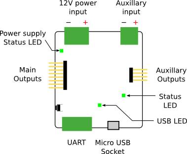
Board Diagram
Indicators
| LED | Meaning | Initial power-up state |
|---|---|---|
| Power | The board is powered | On |
Connectors
There are 8 servo connections on the left-side of the board, and 4 on the right. Servo cables are connected vertically, with 0V (the black or brown wire) at the bottom of the board.
For the servo board to operate correctly, you must connect it to the 12V power rail from the power board. A green LED will light next to the servo board 12V connector when it is correctly powered and the 8 outputs on the left-side of the board can be used.
To use the 4 auxillary outputs on the right-side of the board, 5V needs to be connected to the auxillary input.
Case Dimensions
The case measures 68x68x21mm. Don't forget that the cables will stick out.
Range of servos
When using the majority of servos that we supply, you will find that the servo will only turn about 90 degrees.
Specification
| Parameter | Value |
|---|---|
| Number of servo channels | 12 |
| Nominal input voltage | 11.1V ± 15% |
| Output voltage | 5.5V |
| Maximum total output current1 | 10A |
Designs
You can access the schematics and source code of the firmware on the servo board in the following places. You do not need this information to use the board but it may be of interest to some people.
-
If the auxiliary input is connected, outputs 8-11 have an independent maximum current. ↩