Power Board
The Power Board distributes power from the battery to the rest of the kit. It provides six individual general-purpose 12V power outputs along with a separate power connector for the Raspberry Pi and servos.
It also holds the internal On|Off switch for the whole robot as well as the Start button which is used to start your robot code.
Board diagram
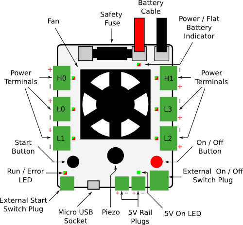
Connectors
There are six power output connectors on the board, labelled L0–L3, H0, and H1. These can supply around 11.1V (±15%). The "H" connectors will supply more current than the "L" connectors.
They should be used to connect to the motor board power input, though can also be used to power other devices. These are enabled when your robot code is started and can also be turned on or off from your code.
There are two 5V connectors that can be used to connect low-current devices that take 5V inputs, such as the Raspberry Pi.
There is also a Micro USB B connector which should be connected to the Raspberry Pi for control of the power board.
Finally, there are connectors for external Start and On|Off switches. You may connect any latching switch for the On|Off switch, or a push-to-make button for the Start button.
Tip
If you intend to use only the internal On|Off switch, a CamCon must be plugged into the On|Off connector with a wire connecting one pin to the other pin on the same connector. Your power board should already have one of these plugged in.
Indicators
| LED | Meaning | Initial power-up state |
|---|---|---|
| PWR|FLAT | Green when powered Flashing red and green when the battery is low |
Green |
| 5V | Green when 5V is being supplied | Green |
| H0–1, L0–3 | Green when the corresponding output is on 1 Red when the output's current limit is reached |
Off |
| RUN|ERROR | Orange on power-up, or USB disconnection Flashing green when ready to run Solid green when running or booting |
Orange |
On power-up and when waiting for the start button, the Power Board will beep once.
If the Power Board starts beeping (and all the outputs turn off) then this means that the whole board's current limit has been triggered.
Controls
| Control | Use |
|---|---|
| ON|OFF | Turns the power board on, when used in conjunction with an external switch |
| START | Starts your program |
Case dimensions
The case measures 83x99x24mm. Don’t forget that the cables will stick out.
Specification
| Parameter | Value |
|---|---|
| Main battery fuse current | 40A |
| Overall current limit2 | 30A |
| High current outputs (H0-1) | 20A |
| Low current outputs (L0-3) | 10A |
| Motor rail output voltage (nominal) | 11.1V ± 15% |
| Total 5V output | 2A |
Designs
You can access the schematics and source code of the firmware for the power board in the following places. You do not need this information to use the board but it may be of interest to some people.