Motor Board
The Motor Board can be used to control two 12V DC motors. These can be used for moving your robot, although don’t feel you are limited to using them for this purpose.
The speed and direction of the two outputs are controlled independently through the USB interface. The USB interface is isolated from the rest of the board to prevent damage to the host in the case of a board failure. Due to this isolation the board must have power applied to both the power connector (from the 12V outputs on the power board) and the USB port. If the board does not have power applied to the power connector then the kit will report that there is a problem with the motor board.
Board diagram
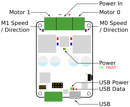
Indicators
| LED | Meaning | Initial power-up state |
|---|---|---|
| Power | The board is powered | On |
| M0/M1 Speed/Direction | Brightness indicates speed, colour indicates direction | Off |
| USB Power | The USB interface is powered | On |
| USB Data | Data is being transferred to/from the board | Off |
Case dimensions
The case measures 70x84x20mm. Don’t forget that the cables will stick out.
Specification
| Parameter | Value |
|---|---|
| Nominal input voltage | 11.1V ± 15% |
| Absolute maximum input voltage | 16V |
| Minimum input voltage | 9V |
| Output voltage | 11.1V ± 15% |
| Continuous output current per channel | 10A |
| Peak output current 1 | 20A |
| UART connection voltage 2 | 3.3–5V |
Designs
You can access the schematics and source code of the firmware on the motor board in the following places. You do not need this information to use the board but it may be of interest to some people.